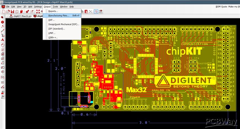
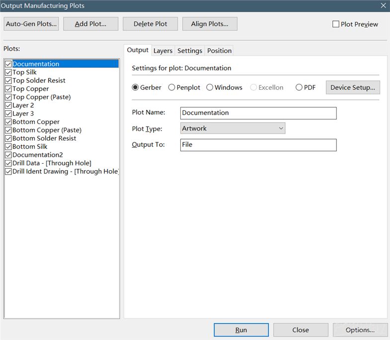
1. Select "Output -> Manifacturing Plots".
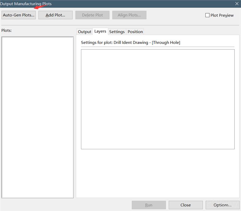
2. Press "Auto-Gen Plots...".
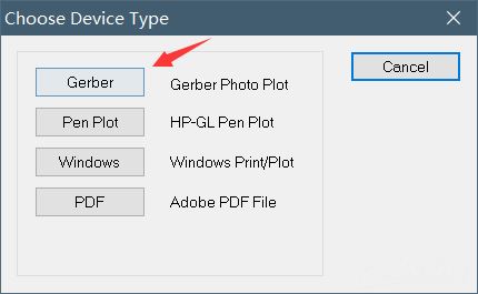
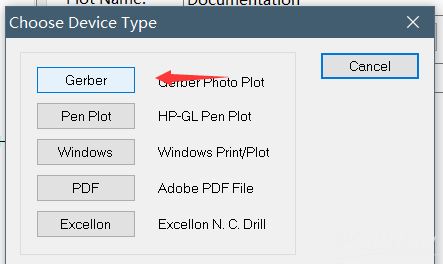
3. Then click on "Gerber".
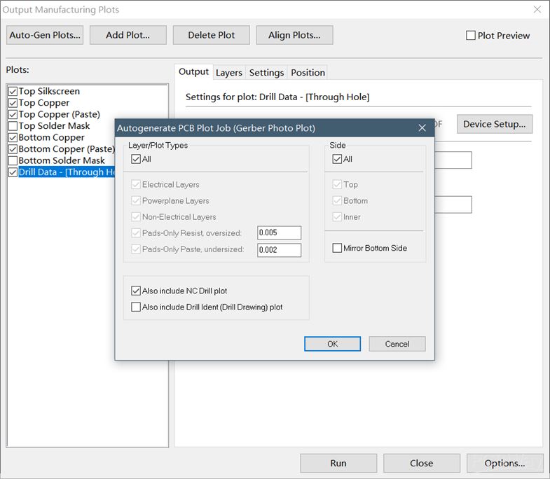
4. There is a pop-up window called "Autogenerate PCB Plot Job". Press "OK" in it.
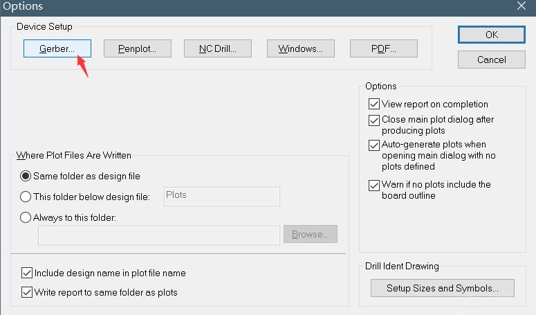
6. A new window will appear called "Options". Here choose "Gerber...".
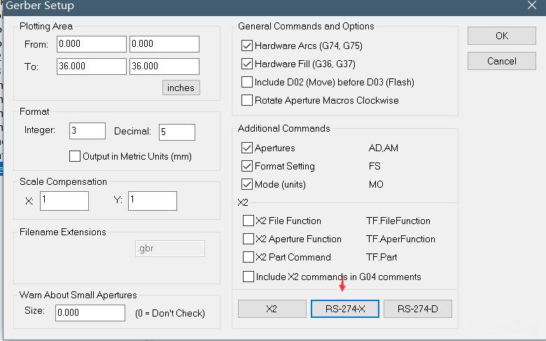
7. In the "Gerber Setup" window choose "RS-274-X". This will take you back to the "Options" window.
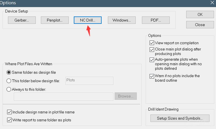
8. Here click on "NC Drill...".
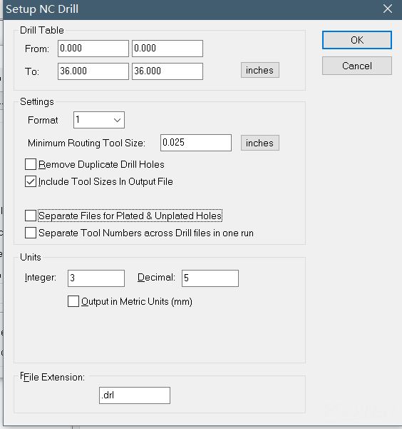
9. This will open the "Setup NC Drill" window. Configure everything according to the picture then press "OK".
10. In the "Options" window press"OK" to get back to the "Output Manufacturing Plots" window.
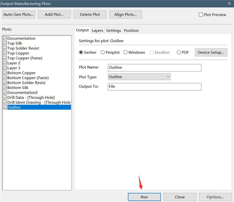
You can see the list of plots on the left. Check the plots you want to create a Gerber file for. To avoid complications, select each element on the list.
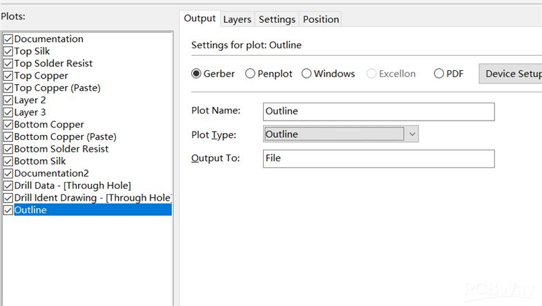
11. If you can't see an "Outline" on the list it has to be added manually.
Click on "Add Plot...".
12. Click on "Gerber" on the next window.
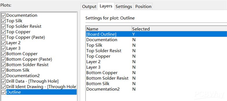
13. Set up the "Output" and "Layers" tabs according to the picture, then click on the "Run" button located at the bottom of the window.
It is recommended that you check the generated files with a Gerber Viewer.
Check the extensions of every generated file according to the table below. Rename them if necessary. After that, put them in a ZIP and then upload it to the Nyákfutár's order site.
Changing the Gerber file extensions
In case of 2 layers:
| Layer | Extension |
| Top Layer | pcbname.GTL |
| Bottom Layer | pcbname.GBL |
| Soldermask Top | pcbname.GTS |
| Soldermask Bottom | pcbname.GBS |
| Silk Top | pcbname.GTO |
| Silk Bottom | pcbname.GBO |
| NC Drill | pcbname.TXT / XLN |
| Mechanical Layer | pcbname.GKO / GML |
In the case of one layer, only the "Top" és "Bottom" files are required.
Additional Gerber files in case of 4 layers:
| Layer | Extension |
| Inner1 layer | pcbname.G2L / G1 |
| Inner2 layer | pcbname.G3L / G2 |
Increasing the number of layers of the PCB will result in more inner layers.


